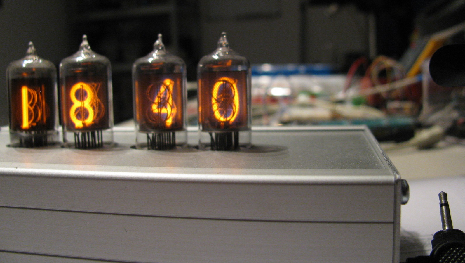
In 2012, sadly my father in law passed away. He was a very good friend and fellow electronics enthusiast. Between the immense amount of electronics parts he left us, I found some ZM1000 Nixie tubes in perfect condition. In addition, there were classic 74141 Nixie drivers. This gave me the inspiration to build a Nixie tube clock, dedicated to him.
Electronics design
There are a lot of resources on-line about all kinds of Nixie tubes and how to drive them. A good resource providing some valuable information and links is Ronald Dekker’s page. Also Onno’s Electronics Page explains how they work and discusses how to drive them. Nixie tubes are cold cathode displays. According to Wikipedia, “The glass tube contains a wire-mesh anode and multiple cathodes, shaped like numerals or other symbols. Applying power to one cathode surrounds it with an orange glow discharge. The tube is filled with a gas at low pressure, usually mostly neon and often a little mercury or argon, in a Penning mixture.”

The tubes need a fair kick up the backside to get the glow discharge going. Starting voltages of typically 170 V are necessary. Once the discharge is started, 140 to 150 V and a few mA of current will keep it going. To provide this kind of power, there are two possibilities: we either supply a high voltage directly by simply rectifying the power from a wall-wart and using some resistors to limit the current, or we boost a lower voltage up to the required value. For many Nixie clock designs on the net, and also for mine, the latter option was chosen.
A 9V DC power supply is boosted by a step-up converter centered around a 555 timer (source: LEDsales australia). The 555 forms an astable multivibrator with C1, R5, and R6. This signal switches a high voltage MOSFET that controls the current through inductor L1. The current change through the inductor causes a rise in voltage over the inductor. As a result, the FET will switch off and a current through D1 charges C6/C7. This repeats itself until the voltage over the trimpot in the voltage divider reaches the threshold voltage of T1 (~0.7V). When this happens, T1 starts conducting, resulting in the control voltage pin of the 555 being pulled low and the multivibrator is stopped. Once the voltage over the trimpot drops below T1’s threshold, the multivibrator is started again. R3 and C2 form a snubber network around the MOSFET. It is a simple low pass filter to prevent voltage spikes to damage the FET.

To control power to the anode of the Nixie tubes (high voltage!) from a microcontroller pin (5V), some driver transistors are necessary (source: jfet.org). MPSA42 and MPSA92 are traditionally used a lot for this job, since they have high breakdown voltages, are cheap and still available from many suppliers. The figure on the right shows the driver circuit of one of the Nixie tubes. The two transistors with some resistors form a current supply for the anode. The cathodes are driven by an archaic but adequate 74141 BCD-to-decimal decoder. This dinosaur has been on the market as long as the Nixie tubes have and it is the perfect choice to control your tubes with a microcontroller. It brings the number of control pins that are necessary down from ten to only four. BCD stands for binary coded decimal, which is a complicated way of saying its a four digit binary representation for numbers between 0 and 9. Because the tubes for the tens of hours and tens of minutes only count up to 2 and 5, respectively, it is even possible bring the number of pins for these tubes down to two or three … which I only realized after the circuit was done …. let’s call it learning on the job.
The clock itself is incorporated in an AVR ATMEGA8535, which I had lying around and now finally found a use for. It contains a RTC (real time clock) driven by a 32.768 kHz watch crystal. I did not incorporate a Lithium battery to keep the clock from forgetting the time when it was off, but that can still be added later, if one would deem it necessary. The clock signal for the AVR was provided by a 10 MHz crystal and all other components on the control board are just connections to the power supply and the Nixie driver board.
Construction

For safety reasons and convenience, the electronics are distributed over three separate PCBs: one for the power supply, one for the control, and one for the Nixie tubes and their drivers. I built the whole thing into an aluminium Proma 1520 box (168 x 103 x 42 cm, Conrad pn. 523224-89) The figure on the right shows the deconstructed clock. I drilled holes in the top plate large enough for the Nixie tubes and glued the Nixie driver board with some spacers to the top plate. That way, I can easily replace the Nixie tubes if they’re broken (let’s hope they don’t, they’re getting expensive…).
The power supply board and the control board are mounted across the box, i.e. the short sides are wedged into designated ridges in the side panels. The buttons to set the time are mounted in the front panel, the power connector in the back panel.

There were two small glitches in the design of the power supply, though. I had thought to bolt both the IRF740 and the 7805 to the aluminium housing, but that would cause a shortcut. I eventually solved this by bolting the 7805 to the box and use a simple piece of aluminium as a heat sink for the MOSFET. Long term temperature monitoring of the heat sink showed that the cooling capacity was adequate. The second glitch is the connection of the power supply. In my design, the power connector was not correctly connected, partly due to the annotation of the connector symbol in Eagle. Usual practice with these kind of barrel plugs is to have the positive pole on the center pin and the ground on the mantle. The Eagle symbol has ‘+’ and ‘-‘ signs next to the connectors, which made me think that the central pin was connected to the ground and the mantle to the positive pole. However, all power supplies with barrel connectors I own, had the positive pole in the center. In the end I solved it by using a power supply with the possibility to switch the poles … very handy.
Firmware

The initialization routine first sets the clock modes of both timer 0 and timer 2. Timer 0 is used to clock the multiplexer of the Nixie tubes. It cycles through the anodes, powering only one at a time to prevent the power supply from overheating. The frequency of the switching from one anode to the next is about 152Hz, enough to prevent an annoying flashing effect and not so high that the tubes can’t follow. The timer 2 triggers an overflow every second to make the clock ‘tick’, so the interrupt handler adds a second to the current time, stored in global (virtual!) variables.
The main loop constantly checks the state of a finite state machine (FSM) with three possible states: CLK this is the running clock mode, the default state. SETH this mode is activated by pressing the SET button in CLK mode, the INC button is then used to adjust the hours. SETM this mode is activated by pressing the SET button in SETH mode, the INC button is then used to adjust the minutes. Pressing the SET button in this mode, selects the CLK mode again.
In each state, the buttons are polled to check for button presses and change the state accordingly. And last but not least, there is a simple function that converts a decimal number to BCD format. It’s only one line:
return (d/10)*16+(d%10);
Download
Eagle and PDF files of the PCBs and the datasheet of the ZM1000 Nixie tube.