I managed to get my hands on an old Haake thermostat bath. My company decided to part with it after the heater had kicked the bucket. Fortunately, I discovered that only the heater control relay was broken, so salvaging the thermostat would be a piece of cake. So much for the thermostat, but what about the control unit? I made one myself on the basis of an Arduino Pro Mini. In this article I explain how I did it, in detail, so it’s a long story.
The bath
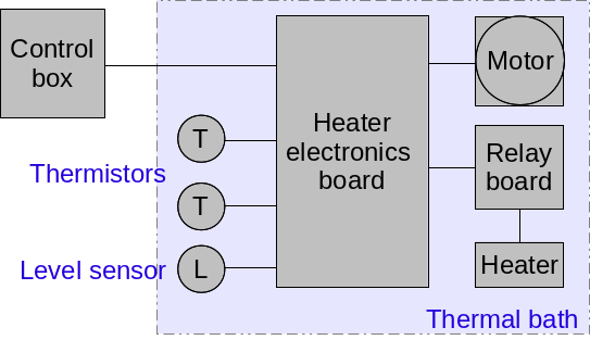
I took the bath apart, cleaned all parts and put it back together. Everything was in order, except for the broken relay and the missing control box. According to the tag plate, it is a Haake 000-8760 bath of about 3 kW. Basically it’s a basin of about 5 liters of water with a heater and a pump in it. The pump has two functions, it stirs the liquid in the basin and it pumps water into an external recirculation loop (which I shortcut for the moment). This particular type of bath is only capable of heating the water, there is no cooler in it. The control system includes a thermostat to control the temperature of the water by switching the heater on and off, and a level switch that turns off the system completely and sounds an alarm when the water level drops below the set minimum or rises above the maximum value.
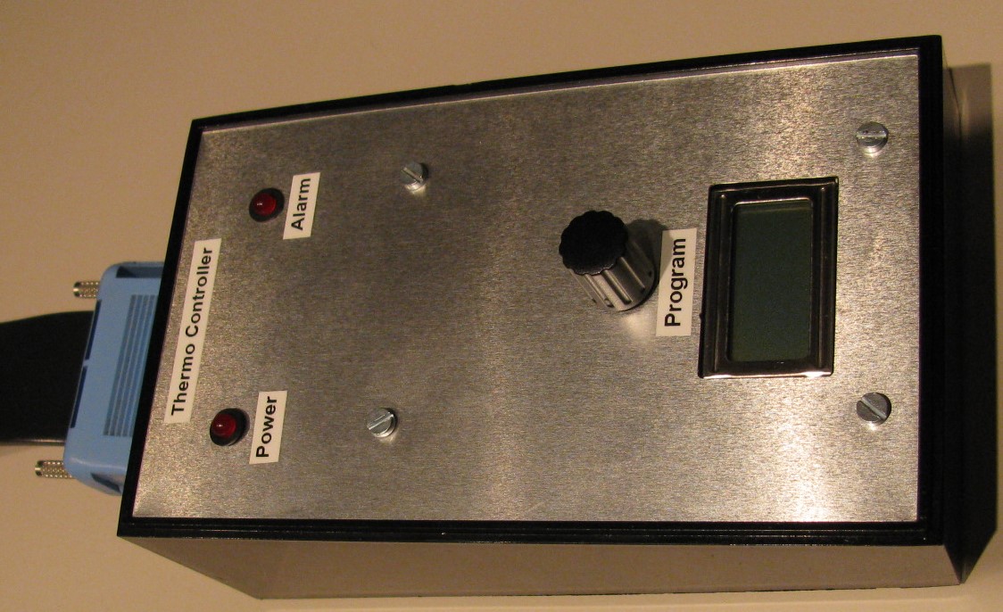
Control box
The control box needs to provide:
- a user interface to switch the pump on and off and adjust the temperature set-point,
- two temperature stable amplifier circuits for the thermistors,
- a pump control relay with a level alarm,
- and a heater control circuit (the relay is on the circuit board in the bath itself).

To minimize noise of switching relays affecting the control circuit, I split the control box in two parts, a power unit and a control unit. The power unit contains a voltage regulator for a stable power supply of the control circuit and the two relays to control heater and pump. The control unit contains the amplifier circuits and the central control unit.
In the download section, you will find a ZIP file containing the schematics, PCB and component layouts of the power and the control unit.
The bath connects to the control box via a 25 pin SubD connector that carries 24V AC. This is converted to 5V DC for the control unit by a rectifier and a simple LM317T regulator with the necessary capacitors. In addition, there are two relays and an alarm circuit on the power unit PCB. One relay is a 24V type that is triggered by the level sensor if the liquid level is outside the limits. The bath electronics already take care of switching off the motor and the heaters, but the relay then triggers an alarm circuit with a buzzer and an LED. The signal is also fed to the control unit that needs to generate an interrupt in the firmware.
The other relay is triggered by the control unit. It switches power to both the pump and the heater whenever the user chooses to start a thermostat control sequence. In addition, there is a transistor on the board that switches a solid state relay (SSR) in the bath itself to control the heater. This sounds complicated, but in essence it’s just a cascaded control system for the heater. In case of an alarm, everything should shut down. However, when the system is running, the pump needs to keep running, while the heater is turned on and off to control the temperature of the bath. Simple actually ….
Electronics

The heart of the control unit is an Arduino Pro Micro (5V version), chosen for its compactness and ease of programming. The digital lines read a rotary encoder with pushbutton that provides the user a means to scroll through menus and select options. User feedback is provided by a 2×8 characters dot matrix LCD. The latter is a standard LCD on the basis of the famous Hitachi HD44780 chip.
The two thermistors are connected to two of the analog inputs of the Arduino, each via a Wheatstone bridge and an differential amplifier. The differential amplifiers are based on a common LM324 quadruple op-amp. All resistors are of the metal film type (1%) to ensure temperature stability of the signal. I know, LM324 does not provide very high precision, nor is it temperature stabilized, but this way I have an affordable circuit that is still pretty reliable. Two op-amps are used in the differential amplifiers, that leaves the other two to provide a stable reference to the Wheatstone bridges. I did a lot of calculations to end up with a circuit that provides an acceptable temperature resolution, while the probability of saturating the op-amps is minimized.
Firmware
First thing to do is the calibration of the temperature sensors. To this end, I started by measuring the resistance of each sensor as a function of temperature in a pan with hot water (see the picture). This gave me a good idea of the linearity and reactivity of each sensor, and I constructed calibration curves for them. It also enabled me to calculate the right resistance values for the Wheatstone bridge and the differential amplifiers during the construction stage.
As a next step, I programmed the Arduino Pro Micro with code that allowed me to switch the pump and the heaters on and off by commands over the serial line. In return, the system gave me the registered ADC values on both sensors. These were used to construct calibration curves that converted ADC values into temperatures. In this process I discovered that one of the two sensors (labeled MESSF on the relay PCB of the apparatus) was very slow and gave large errors. Therefore, only the other sensor (labeled REGELF) is used for the feedback control of the thermostat.

An alarm should be detected in any situation, regardless the current status of the micro-controller. Therefore, a pin change interrupt routine is used to detect the alarm situation and change the display. I’ve had to fit it with a debounce routine, because noise from the power supply or switching relays sometimes caused the interrupt to trigger.
The final step was the tuning the feedback control system of the thermostat. I used the PID library of Brett Beauregard (brettbeauregard.com) and tuned the P, I, and D parameters by running a step change response and registering the bath temperature in time. It turned out that I only needed proportional, because the system was so slow, all fluctuations were already filtered out by the system itself.
Finally, I put it all together with a finite state machine that implemented the menu structure. In the download file I included a PDF file with a schematic drawing of the menu. Currently, the thermostat bath is in use in the flavors and fragrances lab of my brother and it is already functioning flawlessly for a few years.