My friend Joep, whom I’ve known for almost my whole life, has always been a real music freak. He used to DJ at parties of friends and class mates using his own turntables, audio set, and disco lights. Since there were a lot of lights, it was always a heck of a job setting everything up. To solve this problem, we integrated all effects lighting he owned into two giant ‘discobakken’ (disco boxes, literally). When he got married, I gave him small scale exact models of these light effect units. Read on to see how they came out …
Design

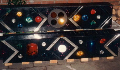
The original design was made by Joep himself when we were about 16 years old, luckily I still had a picture showing the layout of the effect lights (see image, right click to view full size). The top box (box 1) contains a rotating color wheel, next to it on either side are two light bulbs connected to a light organ and there are four additional lights that can be individually switched on and off by the control panel. The bottom box (box 2) contains a strobe light in the center, surrounded by four individually controlled colored lights, a blue, and a red beacon light. The control box (unfortunately no picture…) had several rows of switches that were each connected to the light boxes. Hence, there were 6 (!) wires running from the control box to box 1 and 7 wires running to box 2, 13 wires (!) in total. It was quite bulky, but it did the trick considering we were not that experienced using electronics back then.

Taking measures from the picture and estimating the scale of the picture, I constructed drawings of the boxes and all their constituent parts. I tried to stay as true to the original designs as possible, but it took me a while as some measures were quite hard to determine and not all details came out clear in the picture. The scale of the original is approximately 1.5 x 0.30 x 0.25 m, I scaled it down to 22.4 x 4.7 x 3.5 cm.
Electronics
The main challenges for the electronics were the limited size of the two boxes, supplying power to the boxes and finding a good way to control the light effects. To cope with the small space, I had to minimize the amount of components as far as I could and make the PCB as compact as possible. Initially, I tried to cram batteries into each enclosure to supply the necessary power, but that didn’t work at all. So, the solution would be a power supply plug fitting into one of the boxes and a power line connecting the other box to the first. Regarding the control problem … what would be cooler than controlling it by an IR remote? So I ended up with one ‘master’ box where the IR commands came in, and a ‘slave’ box that received the commands via a standard telephone wire and RJ11 plugs. In its turn, the slave got power from a wall adapter and transported it to the master via the same wire.
Box 1 (the master)

The heart of the master box is an Atmel ATtiny2313, a nice small micro-controller that can be programmed in C using AVR-GCC. To save space, I used the internal oscillator to supply the timing. Next to the standard reset circuit (C5/R15) and an ISP connector (JP6), the individually controlled LEDs (LED6..9) are directly connected to the micro-controller. To limit the current through the micro-controller pins, the motor and the white LED (JP2 & LED5) of the color wheel are controlled via a common emitter driver (Q5/R24). The IR receiver is the well known TSOP1736, powered via a low pass filter as described in the data sheet and connected to pin PD2 of the micro-controller. This pin triggers external interrupt INT0, which is convenient for the firmware to receive commands. The signal of the receiver is passed on to box 2 via a driver (Q6/R30/R31) to prevent overloading the receiver.
Pin PD5 of the micro-controller drives the supply of power to the light organ (via Q1/R2). This is a circuit consisting of a microphone with an amplifier (all components between JP1 and IC1A/R6), a comparator (IC1B/R7/R8), a low pass (C4/R12) and a high pass filter (C3/R9), and a couple of transistor drivers to control LED1..4. I borrowed the idea for this circuit from Burkhard Kainka, who shares the design of a little pocket light organ on his site. The low pass filter has a cut-off frequency of 965 Hz and for the high pass filter it is 15.9 kHz, determined by trial and error … and some frustration. With these values, you get a nicely reactive light organ when music is playing.
Box 2 (the slave)

The slave uses the same controller as the master, with the same reset circuit (R1/C1), an ISP connector (JP2), and the clock signal generated by the internal oscillator. As I already explained, the power connector (JP1) provides power to the slave controller and the master (via the communication line, JP3).
The electronics for this box are a bit simpler than for box 1; there are only 7 LEDs (LED1..7), each directly connected to a data pin of the controller. Each is controlled separately by the IR signals passed on to the slave from the master.
Construction

The boxes are constructed from aluminum plate (1mm) and perspex plate (8 mm). The perspex plate seems rather thick, but I needed enough ‘flesh’ to screw all plates together and to provide enough stiffness. I could have glued everything together, but I did not have chloroform (perfect perspex glue) and could not get hold of it. Anyway, screws also work, but the thickness of the perspex limited the space some more.The aluminum was folded carefully on a work bench, drilled and spray painted.
As you can see in the pictures, box 1 houses the motor with the color disc, 9 LEDs, the IR detector, and the communication line connector. In addition, the electronics needed to be placed near one of the side panels to have access to the sensitivity pot of the light organ. With a lot of fiddling, everything fit in the box. The color disc was constructed from a round aluminum disc of about 4 cm in diameter with four holes in it of 1 cm diameter. Each hole was covered by a piece of foil of a different color. A white LED illuminates the disc while it is rotated slowly by a modified micro servo motor. By removing a notch and replacing the servo pot by a resistor bridge, it rotates continuously when fed with a 50 Hz PWM signal.

Also regarding construction, box 2 was less complex than box 1. It only houses 7 LEDs, a power connector, and a communication line connector. The beacon lights were constructed from clear plastic tubes I got from cheap lipstick; you have to be open to any material source. Didn’t use the lipstick itself, by the way. The bottom plate I turned on my lathe from a piece of Delrin (POM). Through a hole in the middle, the LEDs were positioned in the center of each plastic tube. Red and blue colored foils covered the sides of the tubes to give the beacons their lifelike look.
Firmware

The firmware for the two boxes contain of several separate files to keep things organized. I’ll first talk about the files used/included by the main program files of each controller. The files that are equal for lightboxes 1 and 2:
- global.h: definition of the states for the state machine used in both controllers for receiving IR commands.
- rc5.h and rc5.c: RC5 IR command library based on Atmel datasheet AVR410. I used the IR commands specific to my general purpose IR remote, adapt it to fit yours. The functions it contains are an initializer for the INT0 data pin that receives the IR command, a get-function to retrieve the command in a numeric value, and a timer interrupt handler for command retrieval.
- control.h and control.c: unlike the files above, these are different for each lightbox. Both boxes have a function processCmnd(), for each box it handles the relevant commands.
Light effect programs
lighteffectX.h and lighteffectX.c (where X equals 1 or 2) define functions to control light patterns that are shown on the LEDs that were controlled individually in the original boxes. These are:
- initLEX(): Initialize a timer to provide a heartbeat for showing patterns on the LEDs.
- getPattern(): retrieve the number of the program (sequence of patterns) running.
- switchLEon() / switchLEoff(): switch the light effect on an off
- nextLEPrg() / prevLEPrg(): choose the next or previous program in the list of different programs
The patterns are stored in program memory to save internal memory and a timer interrupt takes care of ticking the counter through the list of patterns. The main program has to check getPattern() regularly to update the pattern displayed by the LEDs.
Signaling lights
signalinglights.h and signalinglights.c define functions to control the LEDs in the beacon lights of lightbox 2. The LEDs emulate the rotating light source in the beacons, so I made the LEDs’ light intensity periodically increase and decrease according to a cosine function. To limit the amount of memory used and keep up processing speed, I programmed the cosine in a lookup table defined in cosine2.h. In addition to the beacon lights, also the strobe light control functions are listed in the signalinglights code.
Main program files
The discoboxes both have a main program file main.c starting with initializers and progressing into the main event loop checking for commands being delivered via IR and processing them.